Referenzen
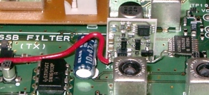
Here are some photos of my installation of the QH40A crystal heater into a standard JRC JST-245 tcvr. The 12 V DC and ground supply are right next to the std oscillator crystal and DC voltage is present when tcvr is switched on. I do have a TXCO for the JST-245 [not installed] but instead I fitted your QH40A, I did not need to remove the synthesiser pcb to enable me to fit the QH40A , it can be fitted without removal of any parts or pcbs. I know some amateurs use the JST-245 as a transverter driver for 2m contesting and EME. I use mine on 50mhz for EME, this morning at 0430z I worked ZL3TY via EME on 6m using JT65A mode, with the JST-245 as my transmitter.
QRA RE57OM > IO91DO = 18,862KM .
Thanks.
Ian Williams M0BCG
.JPG)
.JPG)
.JPG)
.JPG)
QRA RE57OM > IO91DO = 18,862KM .
Thanks.
Ian Williams M0BCG
Hello,
Here are the photos I made for installing properly the QH40A in my Icom
IC-746, using an internal 8V line given by a 7808 regulator in the
tranceiver as supply for the QH40A.
For better thermal stability I used silicon compound between the
reference XTAL and the heater, and I placed cotton arround the
oscillator as showned on the photos..
The mesure I did with my Marconni 2955 (OCXO) Radiocom test set and
Racal Danal 1991 (TCXO) frequency meter give 50Hz drift on 145.000 MHz
when transmitting continuously 5 minutes after 4 hours standing on
receiving (to get the tranceiver warm up).
This give frequency stability better than +/- 0.2 ppm ... and better
than the Icom CR-282 TCXO solution wich is +/- 0.5 ppm.
Best reguards, Gerald - F4AVW.
.jpg)
.jpg)
.jpg)
.jpg)
.jpg)
Here are the photos I made for installing properly the QH40A in my Icom
IC-746, using an internal 8V line given by a 7808 regulator in the
tranceiver as supply for the QH40A.
For better thermal stability I used silicon compound between the
reference XTAL and the heater, and I placed cotton arround the
oscillator as showned on the photos..
The mesure I did with my Marconni 2955 (OCXO) Radiocom test set and
Racal Danal 1991 (TCXO) frequency meter give 50Hz drift on 145.000 MHz
when transmitting continuously 5 minutes after 4 hours standing on
receiving (to get the tranceiver warm up).
This give frequency stability better than +/- 0.2 ppm ... and better
than the Icom CR-282 TCXO solution wich is +/- 0.5 ppm.
Best reguards, Gerald - F4AVW.
QH40A Mod for FT-847
Despite my fan modifications, I was not quite satisfied with the frequency stability on my FT-847, when running high-duty-cycle modes, it would drift up to 3-400Hz on 144MHz after 15-30mins of hard (WSJT, full power) use!
I found a mention of the QH40A Crystal Heater from DB6NT on mods.dk, more information on: http://www.kuhne-electronic.de/english/special/crystalheater.htm , which you place against the appropriate X-tal, to heat it to 40.8° C ±0.1° C
The total price, packaging and postage included (i.e. inside the EU), was € 14.
The heater unit is placed against the Reference X-tal, X1001, and connected to ground and +8-12V
Here the X-tal heater has been placed against X1001 and the wires attached
Jarl, OZ9MO has wrapped a piece of Copper foil around the Crystal before attaching the Crystal heater, in order to improve distribution of the heat to both sides of the crystal. Recommended!
http://www.frenning.dk/OZ1PIF_HOMEPAGE/QH40A.htm
Installation of a QH 40 A crystal heater into an Icom IC-R71E HF Receiver
Following, few details of installation of the QH40A into an Icom IC-R71E HF Receiver.
Given that:
- As there’s no 8 - 12VDC voltages points around, a TA78L10 10 VDC/100 mA Positive Voltage Regulator is needed to drop 13.7 VDC available to 10 VDC, avoiding possible damages to the QH-40 A
- IMPORTANT NOTE: A drop resistor is not reccommended, in order o avoid voltage variations !!!
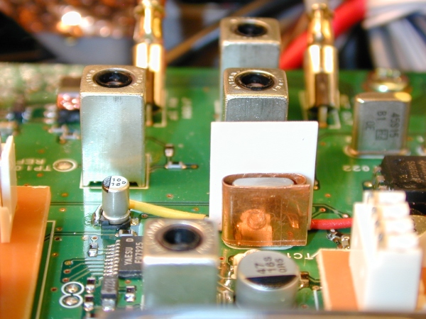
- I spread some silicon paste on the QH40A and the Crystal Face, to allow heat to be better transferred to the crystal enclosure surface.
Procedure for the mod:
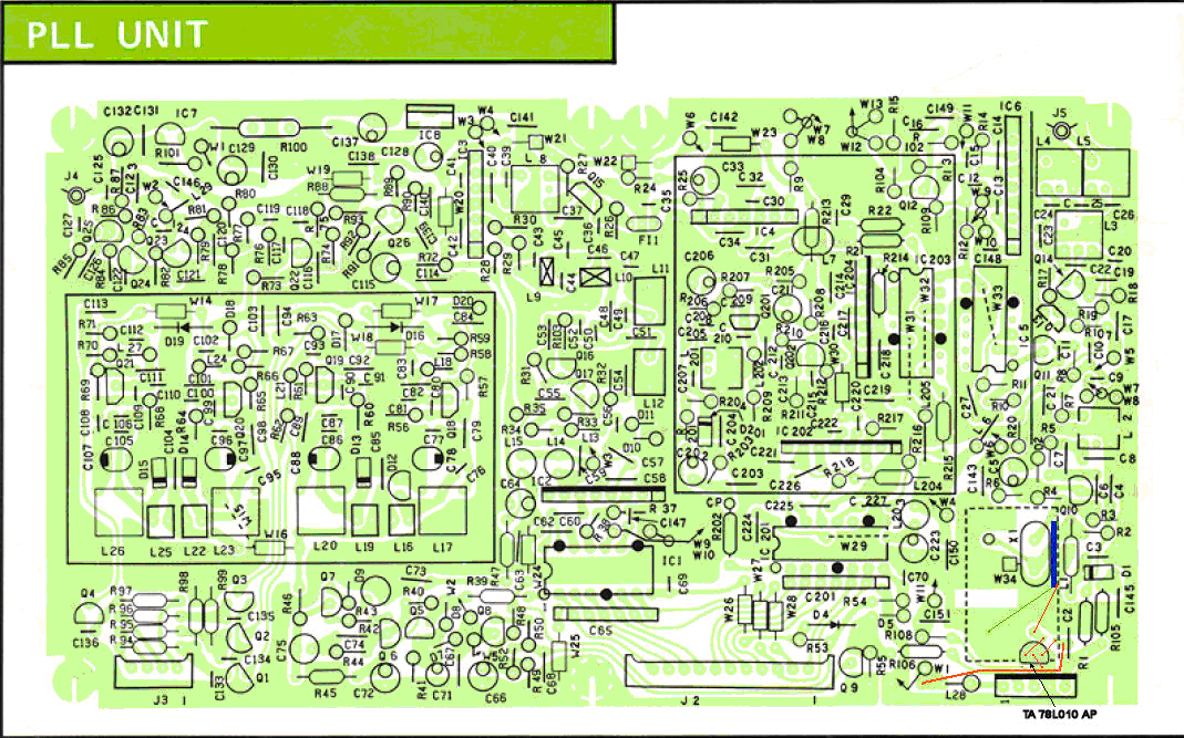
- Locate the PLL Board on the left side of the receiver
- There’s an area on the PLL Board where the main PLL crystal X1 is located. In that area you could install the original Icom CR-64 TCXO option. The drawback is that that option is no more available, and used, really expensive.
- It’s necessary to remove the PLL card carefully removing wire harness (socketed) and two grey coaxes, with slide in plugs. There are six screws holding the board to the cabinet.
- One yellow wire goes to the Main Unit, and it’s single pin socketed. Be careful to unplug it.
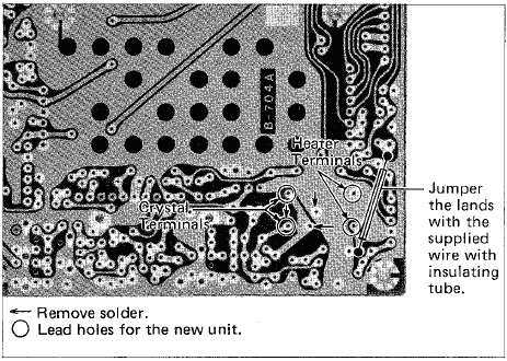
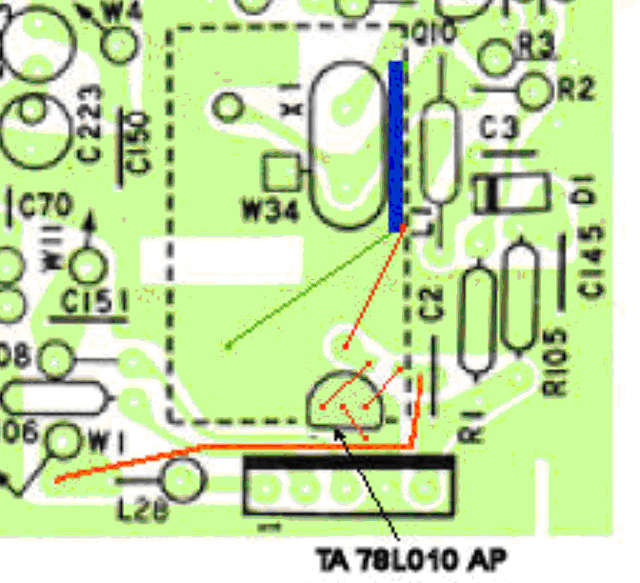
- There’s a wire jumper to solder in order to bring 13.8 VDC on the trace with the purpose of powering the CR-64 (in our case it’s ok for powering the Crystal Heater QH40A). Pls refer to the User’s Manual and/or to the b/w picture attached herebelow.
- Cut with a cutter the the trace powering the CR64 Option, leaving a space of 1 mm, then drill 1 mm hole each side of the trace, possibly close to soldering isles.
- Drill a 1 mm hole in the GND area wherever you’re confortable with the shape of the Regulator pins.
- Mount a TA78L010AP Positive 100mA Voltage Regulator following this pinout:
- PIN1 (Input) goes in the hole corresponding to the Isle where Added Wire Jumper arrives
- PIN3 (GND) goes to the GND hole
- PIN2 (Output) goes in the hole corresponding to the Isle where CR64 would be powered ( in our case where a red wire goes to the left soldering isle of the QH40A )
- Re-adjust Frequency Calibrator Trim (it is located on the bottom of the receiver)
- (do that after 15’ of Burn-In)
Note: Measurements of the DC Power out of the regulator was 9.92 VDC very stable, and the Crystal Quartz Frequency went stable just after 3 minutes.
Enjoy your mod !
IW2FMK
Roberto – Milano
Original User’s Manual Jumperinstructions for powering the CR-64 TCXO
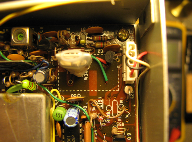
PLL Board layout and componentpositioning
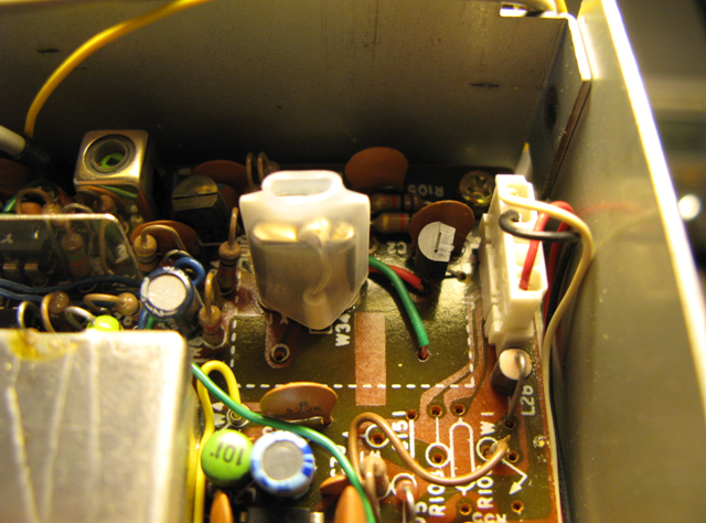
PLL Crystal / Crystal heaterEnlargment
QH 40 A - Umbau des LT2S Transverters auf Betrieb mit Quarzheizer
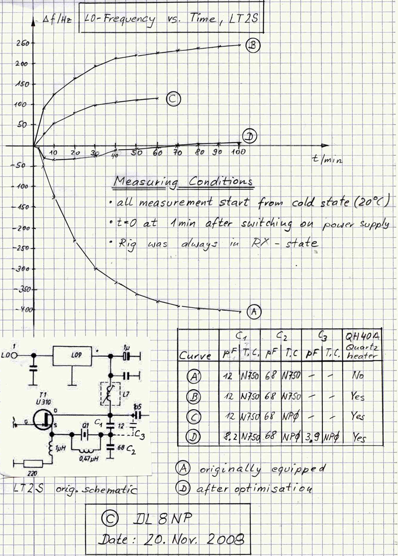
A: Ausgangszustand
B: Quarzheizer QH40A eingebaut, sonst nicht verändert. Quarzheizer-Versorgungsspannung mit 12V Low-Drop Voltage-Regulator stabilisiert. Temperaturdrift TD1 ermittelt (hier ca. 250 Hz).
C: Original C2 (68 pF/N750) durch NP0-Kondensator ersetzt. Temperaturdrift TD2 ermittelt (hier ca. 150 Hz). Aus der Differenz TD1-TD2 die Kombination C1(N750)/C3(NP0) ausgerechnet.
D: Endzustand: Zu C1 = 8.2 pF/N750 wurde C3 = 3.9 pF/NP0 parallel gelötet. Kleinen Lüfter und Kühlkörper auf die Transverter-Box im LT2S eingebaut, damit Schaltungs-Umgebungs-Temperatur nicht über 40°C (QH40A- Regel-Temperatur) steigt.
Diese Bauteile-Werte wurden beim LT2S des Verfassers als optimal ermittelt und können höchstens als Richt- bzw. Start-Werte für eigene Versuche angesehen werden. Die Frequenz-Messungen wurden im RX-Betrieb über die hochstabile Bake DF0ANN auf 144,465000 MHz mit Hilfe der Spectran-Software durchgeführt. Die beim Verfasser erreichte Frequenz-Stabilität nach ca. 2 min. Einlaufzeit (sowohl im Lang- als auch Kurzzeit-Betrieb) ist ausreichend für JT65B EME-QSOs.