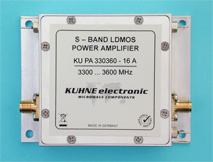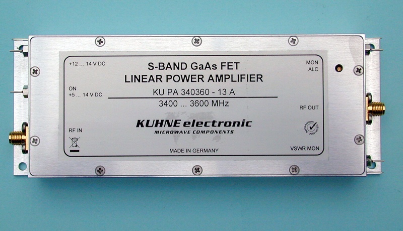
KU PA 340360-13 A, power amplifier
3400 ... 3600 MHz • 13 W
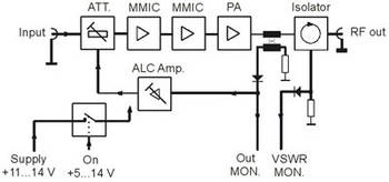
This power amplifier provides high linearity. An isolator at the output protects the semiconductor devices from reverse power. Very good harmonic rejection is achieved. Two detector outputs allow permanent monitoring of forward and reverse power. Typical applications of this amplifier are digital broadcast and communication systems like Digital Video Broadcast (DVB) or Digital Multimedia Broadcast (DMB). The amplifier contains an automatic level control (ALC). The desired output power can be adjusted continuously, from nearly zero to the maximum output power.
This power amplifier provides high linearity. An isolator at the output protects the semiconductor devices from reverse power. Very good harmonic rejection is achieved. Two detector outputs allow permanent monitoring of forward and reverse power. Typical applications of this amplifier are digital broadcast and communication systems like Digital Video Broadcast (DVB) or Digital Multimedia Broadcast (DMB). The amplifier contains an automatic level control (ALC). The desired output power can be adjusted continuously, from nearly zero to the maximum output power.
Lead time on request
| Frequency range | 3400..3600 MHz |
| Input power for P1dB | typ. -13 dBm |
| Maximum input power | 0 dBm |
| Output power P1dB | typ. 41.1 dBm, min. 40.8 dBm |
| typ. 13 W, min. 12 W | |
| Output power P3dB | min. 42.3 dBm |
| Output power COFDM (1) | typ. 34.7 dBm, min. 34 dBm |
| typ. 3 W, min. 2.5 W | |
| Gain (small signal) | typ. 55 dB, min. 53 dB |
| Gain flatness (small signal) | +/-0.5 dB (typ.) |
| Harmonic rejection | min. 45 dB @ 41.7 dBm (CW) |
| IM3 (2) | min. 35 dBc @ 37 dBm PEP |
| Efficiency | min. 24 % @ 41.7 dBm (CW) |
| Input return loss (S11) | min. 13 dB |
| ON voltage | +5 ... 14 V DC |
| Supply voltage | +12 ... 14 V DC |
| Quiescent current | typ. 4.3 A |
| Current consumption @ P1dB | typ. 5 A |
| Forward detection | yes (diode detector) |
| Reflected power detection | yes (diode detector) |
| Operating case temp. range | -20 ... +55 °C |
| Input connector / impedance | SMA-female / 50 ohms |
| Output connector / impedance | SMA-female / 50 ohms |
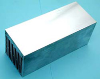
| Case | milled aluminium |
| Dimensions (mm) | 158 x 60 x 20 |
| Weight | 320 g (typ.) |
| (1) | Measured with QAM 64, single carrier, EVM: 2% |
| (2) | Measured 2-tone, frequency spacing: 1 MHz |
- GaAs FET technology
- High linearity (class A operation)
- Good harmonic rejection
- Isolator for protection against high VSWR
- Reverse polarity protection
- Monitor outputs for foward and reverse power detection (DC voltage)
- Adjustable ALC (automatic level control)
- ON / OFF control with DC voltage (ON at 5 ... 14 V DC)
- Digital broadcast systems (DVB, DMB)
- COFDM systems using modulation types QPSK, QAM
- Analog transmission systems
- With reduced power suitable for DATV (digital amateur television)
Please notice the following:
- The technical specifications refer to room temperature.
- The power amplifier doesn’t contain any coaxial relays.
- The recommended combination of heat sink and fan(s) is only specified for an ambient temperature of 25 °C.
- Further information about dimensioning of heat sinks is available on our FAQ site.