KU UP 107 B, Up-Konverter
KU UP 107 B, Up-Konverter KU UP 107 B, Blockdiagramm

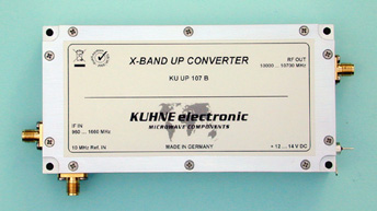
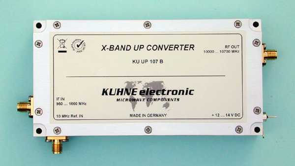
KU UP 107 B, Up Converter

10000 ... 10700 MHz

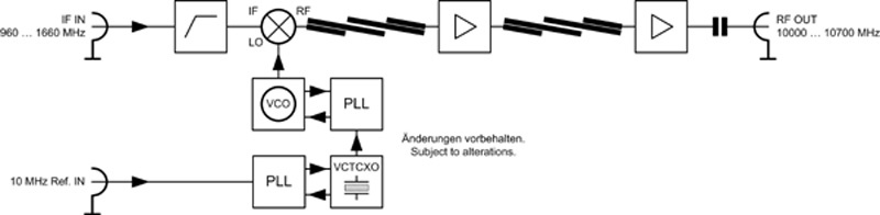
This device converts the IF frequency range 960 ... 1660 MHz up to the frequency range 10000 ... 10700 MHz. Typical applications are MMDS transmitter as well as DVB-T or DVB-S systems. The up converter includes band pass filters for high spurious rejection and a high quality VCO with low phase noise and therefore it is suitable for all modulation types. Together with a power amplifier an output power of 50 watts CW can be achieved.
Lead time on request
Frequency range (IF)960 ... 1660 MHz
Frequency range (RF)10000 ... 10700 MHz
LO frequency9040 MHz
LO accuracy @ 18 °C+/- 2 ppm
LO frequency stability+/- 3 ppm
Phase noise @ 1kHztyp. -79 dBc/Hz
Phase noise @ 10 kHztyp. -83 dBc/Hz
Phase noise @ 100 kHztyp. -109 dBc/Hz
Image rejectiontyp. 80 dB
Gaintyp. 25 dB
Maximum input powermax. 5 mW (+7 dBm)
Output power (P1dB)typ. 250 mW (+24 dBm)
Output power (COFDM)30 ... 60 mW
Maximum case temperature+55 °C
Supply voltage+12 ... +14 V DC
Current consumptiontyp. 850 mA
Reference frequency input10 MHz / 2 ... 10 mW
Input connector / impedanceSMA-female, 50 ohms
Output connector / impedanceSMA-female, 50 ohms
Casemilled aluminium
Dimensions (mm)126 x 64 x 22
Weight310 g
  • Low phase noise oscillator
  • High frequency stability of the oscillator
  • Additional input for 10 MHz reference frequency
  • Automatic activation of PLL if external 10 MHz signal is supplied
  • High linearity
  • Reverse polarity protection
  • Digital broadcast systems (DVB-T, DVB-S)
  • Analog and digital transmission systems
Please notice the following:
  • Additional cooling required

Accessories

References

Radio frequency (RF) and microwave power amplifiers (PAs) are electronic circuits used for the amplification of low power radio frequency signals to high power levels. The most common application of such high-power RF signals is driving of transmit antennas in wireless communications. Since the RF signals are attenuated as they propagate through space, wireless coverage of large areas or wide-range point-to-point connections often require large amounts of transmit power. Another application of high-power RF signals is the generation of strong electromagnetic fields in various types of cavities, where they are used for technical and physical processes like microwave heating, plasma generation, particle acceleration, or in test and measurement setups for EMC tests and characterization of RF and microwave components. Technical applications requiring high RF power levels range from microwave cooking to the treatment and finishing of materials and surfaces as well as medical appliances and optics. The characteristic performance criteria of RF power amplifiers include frequency, RF bandwidth, video bandwidth, maximum output power, energy efficiency and linearity. With his choice of an appropriate power amplifier circuit topology and active device technology (LDMOS, GaN / GaAs HEMT, InGaP HBT, etc…), the RFPA designer tries to find the best possible balance between these, often conflicting, performance criteria, based on the requirements of a given application. For example, a Class A amplifier can be highly linear, generates little harmonics and is rather robust, but is very inefficient on the other hand. It is chosen for applications that demand very high linearity and/or very high bandwidth. In contrast, the Class AB amplifier can be made far more efficient but will not be as linear as the Class A amplifier. It is best suited for applications that demand moderate linearity and bandwidth but benefit from its high efficiency. For applications that require both high linearity and high efficiency, the Class AB amplifier can be linearized using analogue, digital or hybrid predistortion techniques. In very demanding applications like cellular mobile radio or digital terrestrial television broadcast, more sophisticated circuit topologies like the Doherty PA are commonly used to further increase the average efficiency of the transmitter chain while maintaining high linearity. Due to the scarcity of wireless spectrum and the subsequent need for efficient spectrum usage, the wireless communications field is dominated by modulation formats that impose strict linearity requirements on the power amplifier. In contrast to that, the high-power RF signal generators used in technical applications usually generate constant envelope signals at fixed frequencies and thus do not rely on high linearity power amplifiers. Under such conditions, switched mode power amplifiers can be used. By operating the active devices in saturation and application of waveform shaping techniques, these nonlinear power amplifiers enable very high energy efficiencies of up to 80% and more.