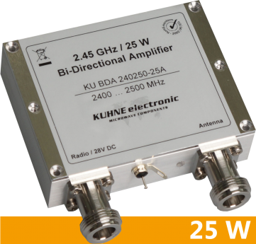


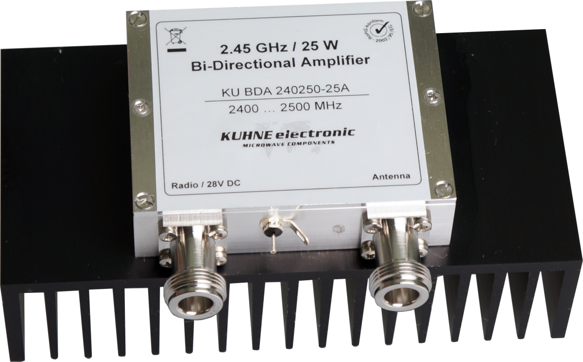
KU BDA 240250-25A, Bi-Directional Amplifier
2400 ... 2500 MHz • 37 dBm COFDM
Mesh-Networks WLAN IEEE802.11 COFDM DVB-T & DVB-S
- No external switching signal necessary
- High operating safety
- Easy monitoring of the operating condition
Lead time on request
| Frequency range | 2400..2500 MHz |
| Switching time RX/TX | typ. 600 ns, max. 1 us |
| Output power P1dB | typ. 44 dBm, min. 43 dBm |
| Input power for P1dB | typ. 20 dBm |
| Current consumption @ P1dB | typ. 2.4 A |
| Maximum input power (TX) | max. 25 dBm |
| Output power P3dB | min. 44 dBm |
| Output power COFDM (1) | min. 37 dBm |
| TX gain (small signal) | typ. 25 dB |
| Flatness TX (small signal) | typ. +/- 1.5 dB |
| Input return loss (TX) | typ. 15 dB |
| Noise figure @ 18°C | typ. 1.7 dB, max. 2 dB |
| RX gain (small signal) | typ. 18 dB, min. 17 dB |
| Flatness RX (small signal) | typ. +/-1 dB |
| Output IP3 (2) | typ. 20 dBm |
| Input return loss (RX) | typ. 15 dB |
| Supply voltage | +27 ... 30 V DC |
| Quiescent current RX/TX | typ. 50 mA / typ. 390 mA |
| Operating case temperatur range | -20 ... +55 °C |
| Radio connector / impedance | N-female / 50 ohms |
| Antenna connector / impedance | N-female / 50 ohms |
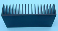
| Case | milled aluminium |
| Dimensions | 81.8 x 63.6 x 22 |
| Weight | typ. 250 g |
| Remote power supply | via radio connector |
| (1) | Measured with QAM 64, single carrier, EVM: 2% |
| (2) | Measured 2-tone, frequency spacing: 1 MHz |
The KU BDA 240250–25 A bi-directional amplifier is designed to support various analog and digital modulation types and signal waveforms in the 2.4 GHz ISM band. The transmitter features LDMOS technology and delivers more than 20 W P1dB power. Switching between transmit and receive path is done automatically depending on the input power level. The receiver’s built-in LNA provides a very low noise figure and additional power gain, which enhances the sensitivity of your receiver.
- LDMOS technology
- RX/TX switching depending on input power level
- Circulator for protection against high VSWR
- Status LED for RX/TX indication
- Remote power supply via “Radio“ terminal
- Additional pin for direct connection of supply voltage
- Digital broadcast systems (DVB-T, DVB-S)
- COFDM systems using modulation types QPSK, QAM
- WLAN applications according to IEEE 802.11b/g
- Analog & digital transmission systems