References
Here are some photos of my installation of the QH40A crystal heater into a standard JRC JST-245 tcvr. The 12 V DC and ground supply are right next to the std oscillator crystal and DC voltage is present when tcvr is switched on. I do have a TXCO for the JST-245 [not installed] but instead I fitted your QH40A, I did not need to remove the synthesiser pcb to enable me to fit the QH40A , it can be fitted without removal of any parts or pcbs. I know some amateurs use the JST-245 as a transverter driver for 2m contesting and EME. I use mine on 50mhz for EME, this morning at 0430z I worked ZL3TY via EME on 6m using JT65A mode, with the JST-245 as my transmitter.
QRA RE57OM > IO91DO = 18,862KM .
Thanks.
Ian Williams M0BCG
.JPG)
.JPG)
.JPG)
.JPG)
QRA RE57OM > IO91DO = 18,862KM .
Thanks.
Ian Williams M0BCG
Hello,
Here are the photos I made for installing properly the QH40A in my Icom
IC-746, using an internal 8V line given by a 7808 regulator in the
tranceiver as supply for the QH40A.
For better thermal stability I used silicon compound between the
reference XTAL and the heater, and I placed cotton arround the
oscillator as showned on the photos..
The mesure I did with my Marconni 2955 (OCXO) Radiocom test set and
Racal Danal 1991 (TCXO) frequency meter give 50Hz drift on 145.000 MHz
when transmitting continuously 5 minutes after 4 hours standing on
receiving (to get the tranceiver warm up).
This give frequency stability better than +/- 0.2 ppm ... and better
than the Icom CR-282 TCXO solution wich is +/- 0.5 ppm.
Best reguards, Gerald - F4AVW.
.jpg)
.jpg)
.jpg)
.jpg)
.jpg)
Here are the photos I made for installing properly the QH40A in my Icom
IC-746, using an internal 8V line given by a 7808 regulator in the
tranceiver as supply for the QH40A.
For better thermal stability I used silicon compound between the
reference XTAL and the heater, and I placed cotton arround the
oscillator as showned on the photos..
The mesure I did with my Marconni 2955 (OCXO) Radiocom test set and
Racal Danal 1991 (TCXO) frequency meter give 50Hz drift on 145.000 MHz
when transmitting continuously 5 minutes after 4 hours standing on
receiving (to get the tranceiver warm up).
This give frequency stability better than +/- 0.2 ppm ... and better
than the Icom CR-282 TCXO solution wich is +/- 0.5 ppm.
Best reguards, Gerald - F4AVW.
QH40A Mod for FT-847
Despite my fan modifications, I was not quite satisfied with the frequency stability on my FT-847, when running high-duty-cycle modes, it would drift up to 3-400Hz on 144MHz after 15-30mins of hard (WSJT, full power) use!
I found a mention of the QH40A Crystal Heater from DB6NT on mods.dk, more information on: http://www.kuhne-electronic.de/english/special/crystalheater.htm , which you place against the appropriate X-tal, to heat it to 40.8° C ±0.1° C
The total price, packaging and postage included (i.e. inside the EU), was € 14.
The heater unit is placed against the Reference X-tal, X1001, and connected to ground and +8-12V
.jpg)
Here the X-tal heater has been placed against X1001 and the wires attached
.JPG)
Jarl, OZ9MO has wrapped a piece of Copper foil around the Crystal before attaching the Crystal heater, in order to improve distribution of the heat to both sides of the crystal. Recommended!
http://www.frenning.dk/OZ1PIF_HOMEPAGE/QH40A.htm
Despite my fan modifications, I was not quite satisfied with the frequency stability on my FT-847, when running high-duty-cycle modes, it would drift up to 3-400Hz on 144MHz after 15-30mins of hard (WSJT, full power) use!
I found a mention of the QH40A Crystal Heater from DB6NT on mods.dk, more information on: http://www.kuhne-electronic.de/english/special/crystalheater.htm , which you place against the appropriate X-tal, to heat it to 40.8° C ±0.1° C
The total price, packaging and postage included (i.e. inside the EU), was € 14.
The heater unit is placed against the Reference X-tal, X1001, and connected to ground and +8-12V
Here the X-tal heater has been placed against X1001 and the wires attached
Jarl, OZ9MO has wrapped a piece of Copper foil around the Crystal before attaching the Crystal heater, in order to improve distribution of the heat to both sides of the crystal. Recommended!
http://www.frenning.dk/OZ1PIF_HOMEPAGE/QH40A.htm
Installation of a QH 40 A crystal heater into an Icom IC-R71E HF Receiver
Following, few details of installation of the QH40A into an Icom IC-R71E HF Receiver.
Given that:
- As there’s no 8 - 12VDC voltages points around, a TA78L10 10 VDC/100 mA Positive Voltage Regulator is needed to drop 13.7 VDC available to 10 VDC, avoiding possible damages to the QH-40 A
- IMPORTANT NOTE: A drop resistor is not reccommended, in order o avoid voltage variations !!!
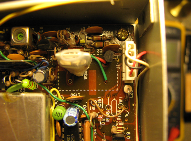
- I spread some silicon paste on the QH40A and the Crystal Face, to allow heat to be better transferred to the crystal enclosure surface.
Procedure for the mod:
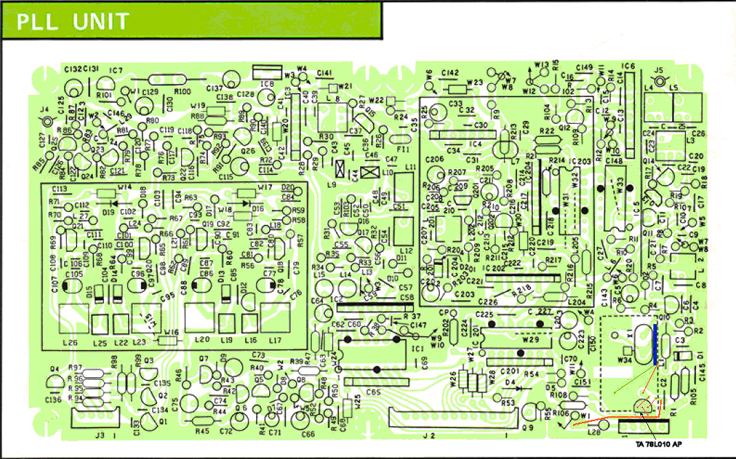
- Locate the PLL Board on the left side of the receiver
- There’s an area on the PLL Board where the main PLL crystal X1 is located. In that area you could install the original Icom CR-64 TCXO option. The drawback is that that option is no more available, and used, really expensive.
- It’s necessary to remove the PLL card carefully removing wire harness (socketed) and two grey coaxes, with slide in plugs. There are six screws holding the board to the cabinet.
- One yellow wire goes to the Main Unit, and it’s single pin socketed. Be careful to unplug it.
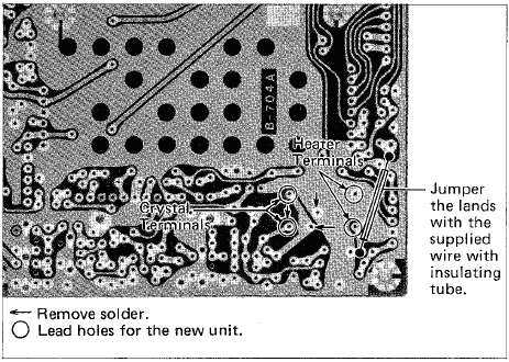
- There’s a wire jumper to solder in order to bring 13.8 VDC on the trace with the purpose of powering the CR-64 (in our case it’s ok for powering the Crystal Heater QH40A). Pls refer to the User’s Manual and/or to the b/w picture attached herebelow.
- Cut with a cutter the the trace powering the CR64 Option, leaving a space of 1 mm, then drill 1 mm hole each side of the trace, possibly close to soldering isles.
- Drill a 1 mm hole in the GND area wherever you’re confortable with the shape of the Regulator pins.
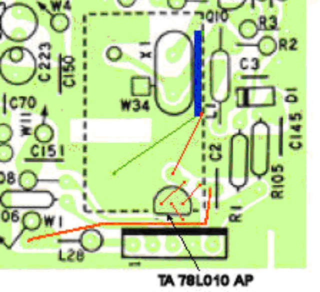
- Mount a TA78L010AP Positive 100mA Voltage Regulator following this pinout:
- PIN1 (Input) goes in the hole corresponding to the Isle where Added Wire Jumper arrives
- PIN3 (GND) goes to the GND hole
- PIN2 (Output) goes in the hole corresponding to the Isle where CR64 would be powered ( in our case where a red wire goes to the left soldering isle of the QH40A )
- Re-adjust Frequency Calibrator Trim (it is located on the bottom of the receiver)
- (do that after 15’ of Burn-In)
Note: Measurements of the DC Power out of the regulator was 9.92 VDC very stable, and the Crystal Quartz Frequency went stable just after 3 minutes.
Enjoy your mod !
IW2FMK
Roberto – Milano
Original User’s Manual Jumperinstructions for powering the CR-64 TCXO
PLL Board layout and componentpositioning
PLL Crystal / Crystal heaterEnlargment
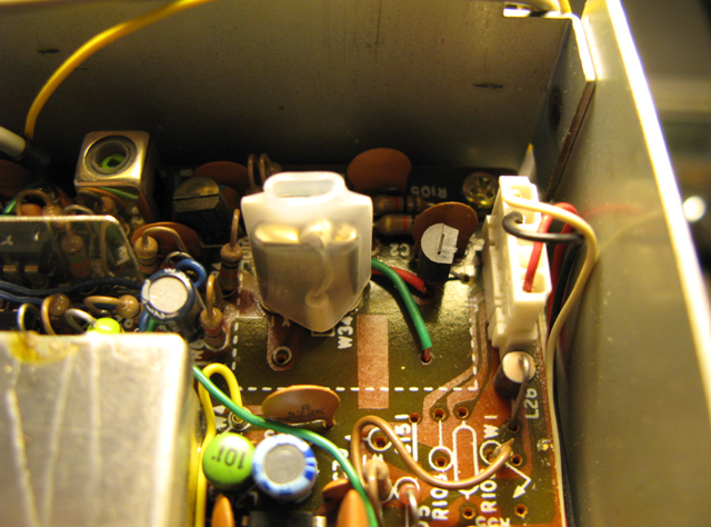
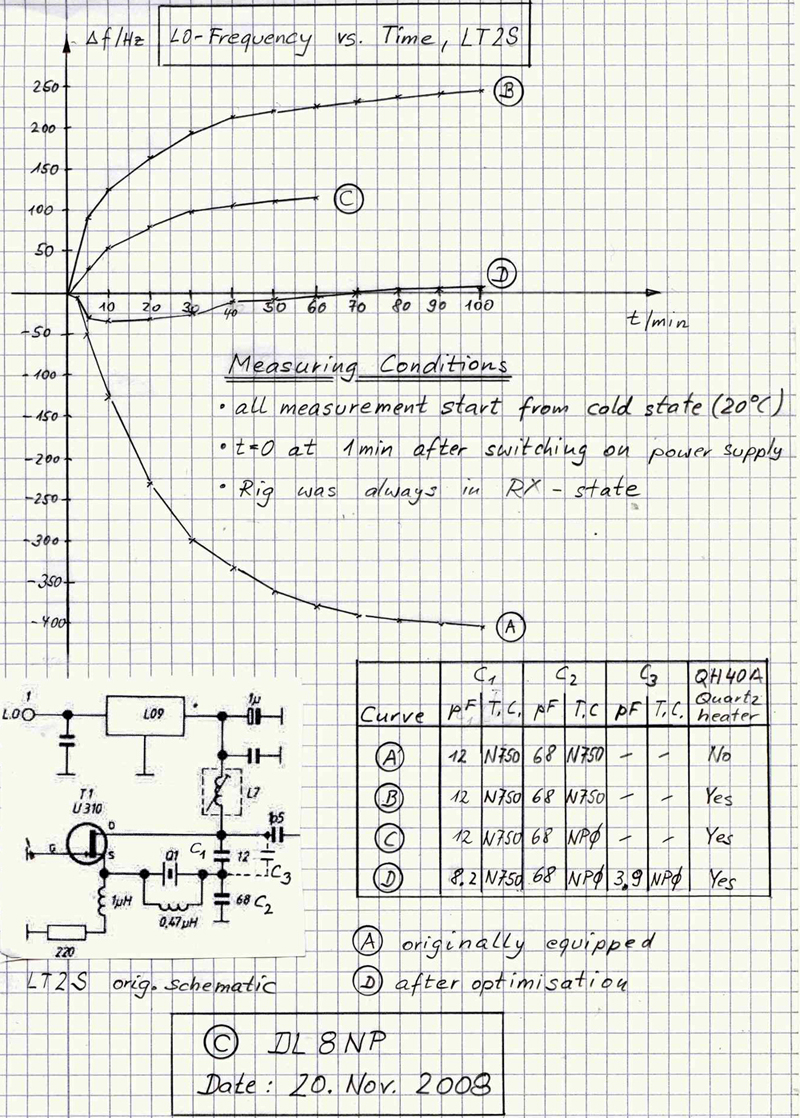
Installation of a QH 40 A into a LT2S Transverter
A: Initial state
B: Quartz heater QH40A installed, otherwise not changed. Quartz heater supply voltage stabilized with 12V low drop voltage regulator. Temperature drift TD1 determined (here approx. 250 Hz).
C: Original C2 (68 pF/N750) replaced by NP0 capacitor. Temperature drift TD2 determined (here approx. 150 Hz). Calculate the combination C1(N750)/C3(NP0) from the difference TD1-TD2.
D: Final state: C3 = 3.9 pF/NP0 was soldered in parallel to C1 = 8.2 pF/N750. Small fan and heat sink installed on the transverter box in the LT2S so that circuit ambient temperature does not rise above 40°C (QH40A- control temperature).
These component values were determined with the LT2S of the author as optimal and can be regarded at most as guideline and/or start values for own attempts. The frequency measurements were performed in RX mode over the highly stable beacon DF0ANN on 144.465000 MHz using the Spectran software. The frequency stability achieved by the author after approx. 2 min. run-in time (both in long- and short-term operation) is sufficient for JT65B EME QSOs.